Table of Contents
Rivanna3S Development Guide
This page is the main source for explanations about development decisions, and how implemented logic is meant to work at a high-level, for the Rivanna3S Embedded Codebase
Project Architecture
At a high level, the project is structured into folders as follows:
BottomDistBoard/,MotorBoard/,RelayBoard/,TelemetryBoard/,TopDistBoard/- these folders hold the application level code for each board. Consider each folder to be the application for that specific boardbuild/- compiled files, not tracked by Gitcmake/,CMakeLists.txt- configuration files for CMake (our build system)Common/- shared classes that can be used in any application codeCommon/Drivers/- classes that represent specific hardware (ex. Uart). These drivers are hardware-agnosticCommon/Libs/- classes that do not represent specific hardware (ex. a queue)Common/Libs/Inc/FreeRTOSConfig.h- configuration for the FreeRTOS kernel. Modifying this is dangerous, only modify with explicit Embedded lead permission!Common/can_structs/- contains the C CAN structs, which are generated from DBC filesCommon/startup.{cpp,h}- this is where the “real” main method is. After doing hardware init, it yields control toapp_main()in each application
Drivers/- for each supported microcontroller: STM HAL files and peripheral hardware init filesMiddlewares/- FreeRTOS and FatFs core code. We don’t modify any of this*.pyfiles - Python scripts with a common use in the development process. See here for info about compile, upload, and monitor
Note that some directories and files of lesser interest are not shown above.
Logging / Printing
Rather than using functions like printf(), we have log functions:
log_debug()for debugging messageslog_info()for informational messageslog_warn()for when something went wrong, but the car does not need to shutdownlog_fault()for when something went wrong, and the car needs to shutdown
These function all have standard printf() functionality, except for printing floats.
To read log messages, connect your laptop to the board, and run monitor.py. Note that the log must be configured before it can be used. In the example below, it is set to the info level, meaning any lower levels (in this case, only debug) will not be logged.
void app_main() {
    log_configure(INFO_LVL, LOG_TX, LOG_RX, 921600);

    // now we can log stuff
    log_info("Starting...");
    int val = 10;
    log_debug("Value %d: " val); // will not be logged due to the log level set in `log_configure()`
    log_fault("Battery fault detected!");
    ...
}
CAN
Controller Area Network is a commonly used serial protocol in the automotive industry. We use this as our main mode of data transmission between components of the car for 2 main reasons:
- Multiple devices can be connected at once. Many serial protocols only support having 2 connected devices at once, like UART.
- All nodes can send and receive messages without central coordination. This removes the need for a ‘central’ hub node, unlike protocols using a Master-Slave Topology like I2C.
There are 2 other benefits as well that come with CAN by default, but could be easily replicated and are common:
- A robust error handling system for when messages fail to send or are corrupted.
- The hardware specification is built on differential signaling, which greatly reduces the impact of electrical noise and voltage supply imperfections.
Terminology
- Node: any device on the CAN network
- CAN bus: the physical communication network
- CAN network: the high-level concept of the CAN bus with all its nodes attached
- CAN frame: a serialized CAN message
- CAN message: data and identifier, in a human-readable format
- Signal: a specific piece of data in a CAN message, like a throttle value
- CAN Transceiver: special hardware that converts logic signals to and from the CAN bus’s physical specification
Defining CAN messages
Each of our CAN messages is defined in a DBC file. This file specifies what data a given CAN message will hold and its identifier; CAN messages cannot be defined ad-hoc, they must meet an already defined specification.
Our Messages are defined here. We use the Python package cantools to read and write CAN messages in Python, and to generate the C structs for each message used in the Embedded Codebase.
Sending and receiving CAN messages in the Embedded Codebase
Start off by defining a CAN Interface at the top of main.cpp for that board.
CanInterface main_can = CanInterface(CAN_TX, CAN_RX, CAN_STANDBY, 250000, CanNetwork::Main);
To send a message, create a CAN struct of the specific message you are sending. Then call .write()
PedalStatus msg{};
msg.throttle_pedal = 10;
msg.brake_pedal = 0;
main_can.write(&msg);
To receive a message, create a function that accepts a const SerializedCanMessage reference as the sole argument, and returns nothing. Note that you will want to deserialize msg immediately if you are doing anything with the structure of the CAN message’s data.
 void handle_dashboard_commands(const SerializedCanMessage &msg) {
    DashboardCommands cmd{};
    cmd.deserialize(&msg);

    // do stuff with cmd...
 }
You must also register this function with the CAN Interface, so it knows to call the function when receiving a certain message type. This should be done in the app_main() function
main_can.register_callback(DashboardCommands::get_message_ID(), handle_dashboard_commands);
See Common/Libs/Inc/CanInterface.h for full details. Note that this architecture is new for Rivanna3S; Rivanna3 and earlier use a very different architecture.
Rivanna3S CAN Networks
The current CAN networks are as follows:
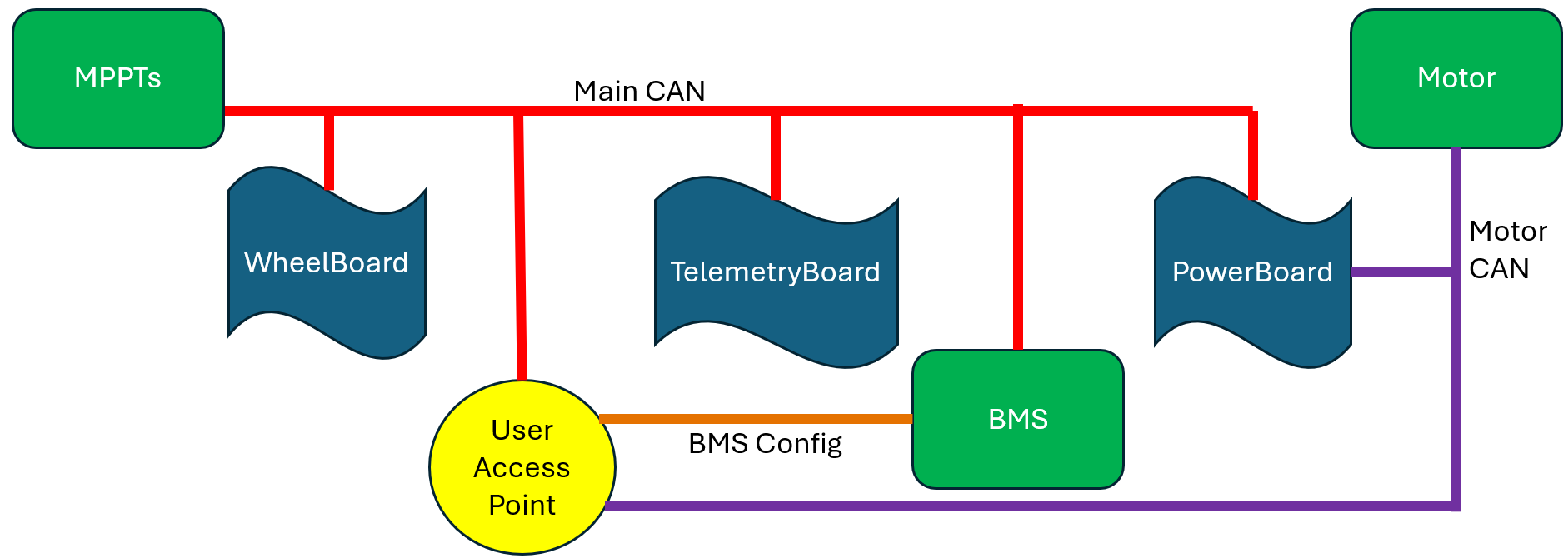
- Main CAN - almost everything is attached to this network, when people say ‘the CAN network’ they mean main CAN
- Motor CAN - connects the motor controller and the MotorBoard
Precharge
Precharge is a system used on the high-voltage part of the car’s electrical system to prevent inrush current. This section refers to the motor, but also applies to the MPPTs as well. Precharge logic and hardware is managed by the Power Subteam; Embedded only implements the logic in software.
Theory
When the motor is connected to the HV system, the circuit can be modeled as a simple RC circuit, because of the inherent capacitance and resistance of the motor. The time taken to charge the capacitor is proportional to resistance * capacitance. By the inherent motor properties, the time constant is small, and the inherent resistance is very small. This results in very high current when the motor is first energized, as the capacitor is charging fast with little resistance; this is known as inrush current, which is bad because it causes extra wear and tear on the motor.
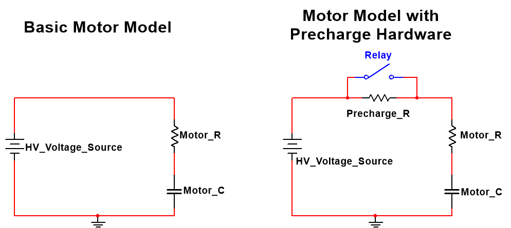
The solution: Add another resistor in series to increase the time constant, and therefore reduce the magnitude of current. This resistor is in parallel with a relay (switch) to enable and disable (short it) it, because:
- The resistor should be enabled when first energizing the motor, to reduce inrush current.
- The resistor should be disabled when the motor is in operation, so the motor can quickly draw the current it needs; the time constant must be minimized for the motor to be responsive.
Embedded implements the logic that controls this relay.
Normal Logic
- Wait until contactor 12 rising edge.
- Wait until discharge_relay_status is high (this signal is sent by the BMS over CAN in the BPSStatus message).
- Close (enable) motor precharge enable.
- Wait until discharge RC voltage is greater than 95% of pack_voltage (this signal is sent by the BMS over CAN in the BPSStatus message).
- Close (enable) discharge contactor, wait a small delay, open (disable) motor precharge enable.
This logic is implemented in the finite state machine (FSM) in RelayBoard/Src/Precharge.cpp.
Note that the process as described is for motor precharge, but MPPT precharge is the same process, just with discharge and motor variables replaced with charge and MPPT variables. Both motor and MPPT precharge processes happen concurrently and independently.
Fault Logic
If at any time (before, during, or after precharge) contactor 12 has a falling edge or a fault occurs elsewhere, then open (disable) the charge and discharge contactor and the motor and MPPT precharge enable relays. Contactor 12 falling edge or many faults in the BPSError CAN message should also cause the BMS strobe light to flash.
Cruise Control
Cruise control is a common car feature that makes the car drive at a constant speed. For Rivanna3S, cruise control is implemented using the PID Algorithm. PID works by setting the output of the motor based on 3 constants. The PID constants can be found in Motorboard/Inc/CruiseControl.h. These should be tuned if cruise control is not effectively reaching the target speed. See PID without a PHD for more information on tuning and PID theory.
Driver Usage
The cruise control target speed can be changed by the driver. There are buttons that increase, decrease, and toggle cruise control. Cruise up / down change the target speed by a constant set in Motorboard/Inc/CruiseControl.h, which is currently set to 5mph.
PhotonicOS

PhotonicOS is the name for the custom real-time embedded operating system that the Embedded Subteam began developing in 2025. The OS sits between our application-level code and the physical hardware drivers. It provides support for multithreading, easier to use drivers, and more.
The team previously used MbedOS, but chose to leave it after it reached end of life, and we bought hardware (the screen in the steering wheel) that MbedOS does not support.
What is included in PhotonicOS
Kernel: We use the FreeRTOS kernel. It provides support for multithreading and concurrency utilities. We created high level C++ wrappers to wrap around the features we use to provide a nicer interface.
Drivers: The manufacturer of our microcontrollers, STM, provides STM HAL drivers, which are C drivers that control the physical hardware. We wrap around these drivers with our own high-level C++ drivers. The key benefit of our C++ drivers, besides creating a nicer object-oriented interface, is peripheral initialization. Through files such as peripheralmap.cpp, application code must only provide the pins of a peripheral instead of the peripheral number itself when initializing a peripheral; this automates the process of determining which peripheral instance supports the pins the programmer wants to use.
File System: a file system only exists on the logging SD card. We use FatFS for this.
Devops: there are multiple Python scripts we have to ease development operations: upload.py to abstract flashing code to a microcontroller, compile.py to abstract the compilation system, monitor.py to read log data from the microcontroller, and code generation scripts.
Adding new features
Not hardware related: (example: adding a class to process data)
If this library will only be used by a specific board, put the code in that board’s folder, otherwise put it in Common/Libs/.
Hardware related: (example: adding support for OctoSPI peripherals)
- Find the STM HAL driver for the new peripheral.
- Write a C++ wrapper for the peripheral in
Common/drivers/, and make sure to updateperipheralmap.{cpp,h}as needed to handle looking up which pins are associated with which instance of the peripheral. - Test
- Update the code generations scripts in
Drivers/code_generation/to handle the new peripheral. - Follow the steps in “Adding support for new microcontrollers” below to regenerate driver code for all microcontrollers, to ensure all microcontroller can run your new code.
Adding a new board
Example: creating a new board called MiddleBoard, which will use an already supported microcontroller.
- Add the following files to the repo
MiddleBoard/Inc/pindef.h: pin mappingsMiddleBoard/Src/main.cpp: application code, remember to have anapp_main()function defined hereMiddleBoard/CMakeLists.txt: compilation configuration, can be largely copied from other boards
- Add MiddleBoard and the location of its compiled
.elffile to theBOARD_MAPdictionary inupload.py
Adding support for new microcontrollers
Example: adding support for the STM32xyzABCx microcontroller
Warning: PhotonicOS was designed for exclusive use with STM32 microcontrollers. Adding support for other brands of microcontrollers will be a lot of work!
This video walkthrough covers steps 2 through 7 below.
- CORRECTION: step 4 below was missed
- Install STM32CubeIDE
- sign in with your myST account
- Create a new project for the STM32xyzABCx microcontroller, then open the
{project name}.iocfile - Enable all the peripherals the team uses (ex. UART, I2C, SPI)
- note that UART, USART, and LPUART are functionally the same and can be used interchangeably while I2S is not I2C and QuadSPI or OctoSPI is not SPI
- for the ADCs, only 1 channel needs to be enabled. If given the option to choose between double- or single-ended, choose single-ended
- Enable FreeRTOS in Pinout & Configuration » Middlewares and Software » FREERTOS » CMSIS_V2. Then change the HAL timebase to another timer in System Core » SYS » Timebase Source » TIM1.
- If you see a red symbol next to the Clock Configuration tab click that and follow these instructions
- In the middle-left of the page, your goal is to set the
PLLQandPLLPclocks. Change the dividers and multipliers until both values are 40 (MHz). Depending on the microcontroller size, there might be multiple PLLQs and PLLPs - Set all the peripherals the team uses to use one of these clocks. Each peripheral has a different range of acceptable clock speeds, but all peripherals seem to accept 40 MHz as valid.
- In the middle-left of the page, your goal is to set the
- Open the Project Manager tab and make these changes
- in Code Generation, check Generate peripheral initialization as a pair of .c/.h files per peripheral
- Save the file, which will then autogenerate the needed files
- you can ignore the warnings given before generating code
- See
Drivers/code_generation/Readme.mdto finish. The scripts it describes will import the files that STM32CubeIDE generated and make automatic changes to them so they work with the rest of our codebase - You will likely need to adjust the time source for FreeRTOS and maybe HAL. This involves adjusting some interrupts; its probably better to let AI do this since it can vary a lot.
- if both are working, then you should be able to blink a light from
app_main()without issue - to test if HAL time is setup correctly, add code to
Common/startup.cppto flash a LED. Add a while loop to do this AFTERstartup_init()but beforevTaskStartScheduler(), and useHAL_Delay(1000)as the sleep function. If the light flashes, then HAL timebase is set properly. If it turns on but doesn’t flash, then the HAL timebase is not properly set. If nothing happens, then you probably made a mistake elsewhere.
- if both are working, then you should be able to blink a light from